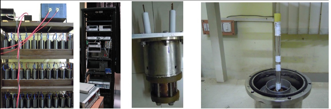
35 tesla pulsed
field facility at IISER Kolkata
The
small value of the permeability of vacuum implies that an extremely high current
density (∼ 1 MAcm-2) is needed to generate a magnetic field of
one tesla. Since the maximum field strength of superconducting
magnets is presently limited to about 20 tesla, one has to rely
on resistive conductors to generate higher fields. The power
consumption of these high field resistive magnets runs into
megawatts and these are therefore only feasible in the few
large-scale multi-million dollar infrastructures like the ones
in Grenoble, Nijmegen, Tallahasse and Tsukuba.
An elegant way around
this problem (and to also achieve even higher magnetic fields),
is to generate very large power for only a very short time as a
transient pulse. Consequently the total energy requirements can
be limited to about a hundred kilojoules (about the energy
contained in a cup of coffee) and one can still achieve fields of
about 50 tesla. Depending on the size of the installation, anywhere between a
few kilojoules to a few megajoules of energy is stored in a bank
of capacitors which are discharged through a solenoid wound with
a resistive conductor (e.g. copper). The constraint of heating
is kept under control by the time duration for which the field
is generated (10–1000 milliseconds). During this time the magnet, which is immersed
in liquid nitrogen, adiabatically heats up to around room
temperature. The experiment can be repeated once the magnet has
cooled down again.
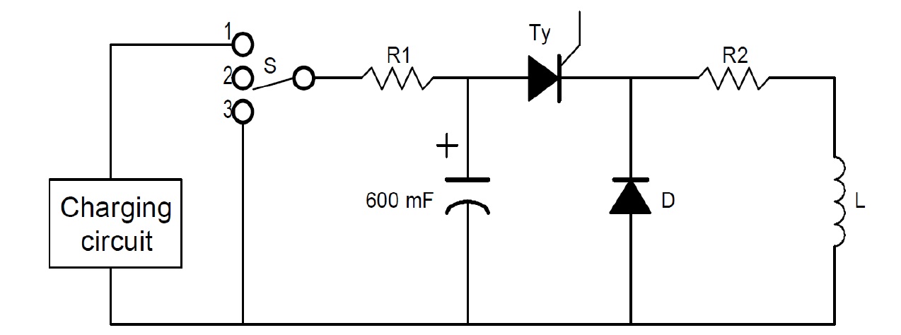
Schematic
circuit of a pulsed magnet. It is essentially an LCR circuit.
A bank of capacitors (600 mF in our case) stores
energy which is
rapidly discharged through a suitably designed solenoid with
resistance R2 and inductance L. The thyristor (Ty) is used to
close the circuit and the diode (D) prevents oscillation of
current.
Our set up has the
following modules:
• Capacitor
Bank—The capacitor bank (75 kJ) comprises of 60
electrolytic capacitors, 10 mF each with a peak voltage of 500V,
connected in parallel. The capacitors are made by a Pune-based
company (Alcon) and the bank was wired by the students here.
• High Power
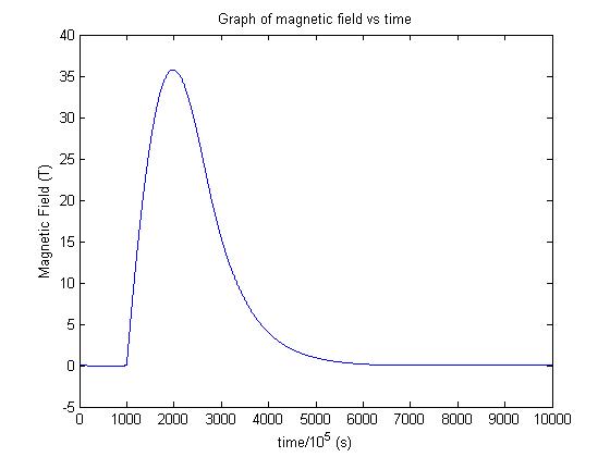
electronics and switching—The magnet is energized with a
transient current pulse of about 20 ms duration and a peak
current of about 25 kA. This requires a high current electronic
switch (thyristor) that completes the circuit after receiving a
trigger pulse and a crowbar (power diode) to prevent the LCR
circuit from oscillating. Both these were purchased from the
market in Kolkata.
• Magnet Coil—
For pulsed magnets the fundamental constraint on the peak field
is only the strength of the conductor wire which has to withstand the massive
Lorentz force. For copper the limit turns out to be around 30
tesla. By a careful design that involves reinforcing the conducting wire with a high
strength fibre composite and distributing the stress within the
volume of a coil, the peak field can be increased by about a
factor of two.Our coil has a 16 mm bore with 7 layers of
winding, each appropriately reinforced to withstand the stress
at 35 tesla. Since winding such a coil is an a very specialized
task, Dr Tao Peng (of Wuhan University of Science and
Technology, China) improved our design and wound the coil for
us.
• Low temperature
cryostat—Since we do not have access to liquid helium, we
have developed a magnet cryostat around an old 4 K helium closed
cycle refrigerator having a sapphire (thermal conductor and
electrical insulator) cold finger. Currently, the temperature
range accessible is about 6 K to 300 K.
• Electronics for
synchronous data acquisition—The trigger pulse that fires
the magnet also triggers a high speed data logger (20MHz, 16
bit, 4 channel). A low noise voltage preamplifier and ac or dc
current source is used to excite the sample. We can do Hall
effect and magnetoresistance measurements.
• Digital Signal
Processing—Measurements in a pulse magnetic field, by
their very nature, are noisy. Thousands of amperes of current
suddenly flows through the magnet coil, giving the whole set up
a large mechanical impulse. Moreover, the changing magnetic
field superimposes a large inductive pick up on the sample
signal. To get around this, following by now a routine practice,
we have developed a high frequency digital lockin amplifier
where the sample is excited at around 1MHz and the sample signal
and the reference
waveform during the pulse are stored. The lockin procedure
(multiplication and low pass filter) is later digitally
implemented using Matlab. Due to the short time of the pulse,
commercial lockins are not suitable for transport measurements
in pulsed fields. While the software part is implemented
and working well, we are still trying to get around the large
cable capacitance and inductance that interfere with the high
frequency measurement.
• Magneto-photoluminescence
spectroscopy (Under development)—We have recently
acquired very sensitive electron-multiplying charged coupled
device camera-based spectrograph that would allow us to record
luminescence spectra synchronized with the pulse. The associated
fibre-optics assembly and cryostat are not ready yet.
You may write to Bhavtosh
Bansal [bhavtosh[]iiserkol.ac.in] for more information about
the set-up and its capabilities and/or if you are interested
in trying some magnetotransport measurements. If you have an
interest in setting up such a facility in your lab, we would
be delighted share our expertise and resources.
Acknowledgement:
Dr Tao Peng for improving our coil design
(designed using the software developed by him) and most
importantly winding it for us!
Group
Md. Arsalan Ashraf (PhD)
Subhrajit Guin (PhD)
Sujeet Kumar Choudhury (MS thesis)
K Sujith (MS thesis)
Dr Pradip Khatua
Dr Uday Kumar
Bhavtosh Bansal
Short-term project students:
Sumitabha Bramhachari (IIT Bombay, summer 2012)
Abhilash Paswan (IISER Kolkata, summer 2012)
Ujjwal Nandi (IIT Bombay, summer 2012)